21.9.10

Stuck at the station

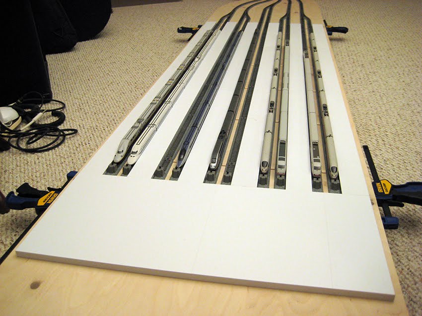
I thought displaying all my bullet trains on the platform module might give me some inspiration designing the station building. No such luck. I sit here pulling my hair, trying to work things out in my head. The difficulty is that I have to design something that is esthetically pleasing to look at, yet easy and quick to construct. Curvilinear lines present a challenge to schedule due to logistics, but I do like how they look architecturally.

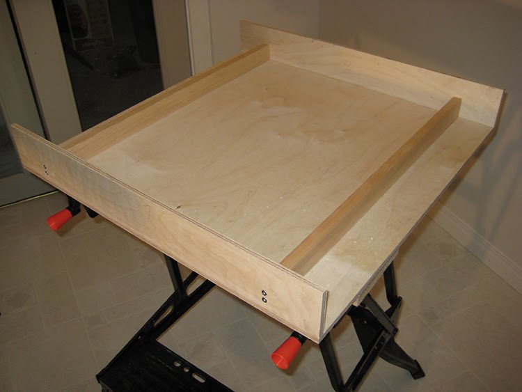
At least the foundation connecting the individual track platforms is finished as you can see. This was influenced by my experiences in München visiting the main station. I had considered a station similar to the one in Köln, but I was concerned about the curved roof structure. The styrene plastic tends to become brittle when exposed to the solvent. The other concern is how the ceiling structure blends with the platform ceilings. I want it to be cohesive. This is fast becoming a difficult challenge. The problem stems from the limitations of the material I am working with. If only I had unlimited and unfettered access to a large scale, high resolution 3D printer. My cousin's husband mentioned a company called MakerBot, which sells a 3D printer kit you assemble yourself. I had considered getting one except the resolution is too coarse for my liking. The other drawback is it can only produce small models. Unfortunately, I have grandiose plans that exceed my skill set and free time. Sigh. Back to the drafting table.

19.9.10

Praha hlavní nádraží

Work on the station has begun. Right now, I'm just cutting and gluing the styrene pieces together for the foundation. I'm still trying to work out how the building structure is going to look. As I wait for the plastic and solvent to dry, I thought I'd sort through my photo archive of Praha hlavní nádraží. Jerry from Quinntopia had commented on one of my older blog entries that the tracks leading into the Prague station were almost identical to the look he was trying to achieve for his new station layout. So I thought I'd help out a fellow modeler and post a few more pictures for reference material. I included some interior shots. My apologies for the poor quality. The interior lighting was very dim.


12.9.10

Update

It's been a most productive week-end. The benchwork is complete except for the painting. I've drilled the holes for the cables, patched up the gashes and sanded the tables. I'm planning to lay the unitrack on the tables without permanently securing them. I didn't want to have to rig a scheme to connect the tracks at the edge of each module. It will also allow me to quickly store the modules without fear of damaging the track work since they will be packed in storage bins during transport. That is, if I ever decide to take my layout to shows. As a consequence, I had to install track guides. These help to keep the tracks in alignment with each other. The guides are simply rectangular pieces of wood glued strategically on the table surface. I went to many home renovation stores hoping to find some thin strips of wood. None of them carried anything small enough. I went to Michael's, but they only had balsa wood, which is too soft. After driving all over town, I finally came across a hobby shop that sold mixing sticks for stirring epoxy. They're essentially popsicle sticks, but they work. I just wished I didn't have to spend the whole afternoon driving around town.

The unitrack has been put back onto the layout and the cables have been strung through the new openings in the tables. There are a lot of wires! The biggest difficulty will be making sure the cables are connected correctly to their controllers. I'll likely go to a computer store this week and get tags to help easily identify the cables. I also placed an order for more 3-way extension cords so it will be a few weeks before I can test my switches/turnouts. In the meantime, I'll need to figure out how to rig up a switching device to control the power feed to the four main lines. I'll head over to Active Electronics and check out their inventory of rotary switches.

9.9.10

Switching

I've suspended disbelief and accepted the in-congruent realities of Shinkansens operating next to Inter City Expresses in Hel. However, I couldn't come to grips with having to control all eighteen turnouts on the layout. I was trying to figure out a way to make the task of switching less arduous.

Each turnout has a single solenoid built into the ballast running on direct current (DC). The solenoid is connected to a controller (Kato part #24-840), which is a momentary contact double pole double throw switch. I wondered if it was possible to control two turnouts with a single Kato control switch. I would have to splice two sets of cables to a controller, but I was more concerned if this might cause electrical problems with the turnout motors or the power supply.

Based on my research, six switches can be thrown simultaneously on a single power supply. Although there is no limit on the number of switches that can be connected to a single power supply. You just can't throw all the switches simultaneously otherwise it will short out the power supply. With care, I can avoid overloading the power supply.

The other and greater cause for concern was whether using a single switch to control two turnouts would cause the turnout motors to burn out. Those turnouts are quite expensive! Determining that it was possible to control two turnouts with a single switch, I was preparing to splice wires until I came across a thread on a forum about the 3-way extension cord (Kato part #24-827). It so happened that I had purchased one a long time ago for the purposes of providing power to several sections of the track. It never occurred to me that I could use this device to control up to three turnouts with a single switch. The little pamphlet that came with the extension cord even describes this alternate usage. I guess I had assumed the use of the device was reserved only for power due to the blue/white coloration of the wires. Whereas the wires for the switches and turnouts are colored red/black. It pays to read manuals as I saved myself from the unnecessary task of splicing and soldering wires. As a consequence, I managed to reduce the number of switches to twelve. Here's a short video of two turnouts being controlled by a single switch.


6.9.10

The first spike ...

The foundation for Hel Hauptbahnhof has been laid with the completion of the bench work. I was cutting wood much too late last night hoping to finish the final section. Unfortunately, I had to wait for the glue to dry before installing the support frame on the reducer module so the work didn't finish until today.

Due to the unusual curves of the reducer module, I had to be creative with the placement of the underlying framework. The shallow angles exceeded the range on my mitre saw so it took a lot longer because I had to iterate several times to get the correct angle. All in all, I'm pretty pleased with the result. The warp in the plywood has straightened out and the modules all align. I still need to drill holes for the turn-out cables, fill large indentations with wood putty and sand, but all the difficult rough work is complete. Now I can begin designing and building the architectural structures during the winter months. I'll likely tackle the foundation of the railway station first as it is the least complicated of the structures on this layout.


4.9.10

Labouring on the layout

Construction of the benchwork begins this Labor day long week-end. The forecast calls for rain all week-end so it's a perfect excuse to stay indoors and work on the train layout. In total, there are four modular sections. The layout is composed of a station, platform, reducer and bridge section. I elected to combine the interchange with the bridge to shorten the already lengthy layout. Doing so gave me more space to add the station extension, which is what I assembled today.

There are only end walls where the tables connect. I excluded the side walls so that the entire layout would look like it was on a thin shelf. It's a l
ittle difficult to explain what I am doing here, but I wanted it to appear that the entire layout was one thin sheet of plywood. Where the tables join, I will have some sort of table leg-connector, which will conceal the edge of the end wall. I haven't fully vetted out how this will be done, but I'll post pictures when I've sorted it out in my mind. It may be a while. I tend to over think things too much. Worse case scenario, I can always put on side walls if my plans don't work out. I'd like to avoid that as much as possible because it would require me to bend wood for the reducer section. Something I am loathe to attempt with my novice woodworking skills. It took me all afternoon to finish assembling the section for the station module.

In the photograph on the left, you can see the extensive use of clamps. I have to say they were indispensable as I glued the end walls to the bottom of the table top. I'm glad I picked up all these clamps when I started this layout. Although I appreciate the quick release of the Irwin clamps, they're not as sturdy nor as strong as a typical C style clamp with the threaded bolt. The Irwin pinch clamps are even weaker. I don't think they sell them anymore. The spring clamps have a tighter hold than the pinch clamps.

This photograph shows a close up of the 90 degree assembly braces. I bought the braces from Lee Valley specifically for this job. They were a bit expensive, but worth it! With the clamps, the braces definitely helped to keep things properly aligned while the glue set. As I said before, it pays to have the right tools for the job.

Just as a precaution, I hammered in nails to make sure the pieces would not separate. I first drilled a small hole to prevent the plywood from splitting as it is only 3/8" thick. Angling the nails will ensure the two pieces do not lift apart. By the way, the strips are only 3" wide. I wasn't expecting the tables to bear a lot of weight so I felt this width was more than adequate. I had these cut at Windsor Plywood as I do not have a table saw. It was well worth the shop fee to have them cut the plywood for me.

Lastly, I attached two 1" x 2" fir strips under the table top to prevent sagging. It took me all afternoon to assemble the station module. I'm expecting the other modules to go much faster now that I've sorted out the details. Hopefully I'll be able to post a picture of all the modules completed after this long week-end. Fingers crossed.